Gibson Girl M 357a
Thanks to Air Historical Branch (RAF) - Ministry of Defence (Londres-GB) Royal Air Force Museum - Department of Research (Londres - GB) to give us these informations and these documents |
| Home Gibson Girl (wokipi-kite) | Extract "Air Publication" | Origin of name | |||
DINGHIES AND ASSOCIATED EQUIPMENT (NAVAL), Vol. 1, Sect. 6, Chap. 1 |
Extract of Manual : ......... Signal lamp 10. There are two types of signalling lamp, namely : : (1) One with a flat lens which makes the lamp directional. (2) One with a dome-shaped lens which makes the lamp non-directional. A strap is provided which fastens at the back of the operator's head, and if the lamp is directional it can be fixed on the forehead. When the non-directional dome-shaped lamp is provided, the strap tics under the chin so that the lamp is on the top of the head. 11. The lamp is plugged in the socket provided for it at the top left-hand corner of the front panel. Spare reel of aerial wire 12. Should the original aerial be carried away, it can be replaced by the spare reel of antenna wire (fig. 2) which is carried in the stowage bag. The wire on this spare reel is wound on backwards so that it may be run on to the reel inside the winch door, after that reel is empty. |
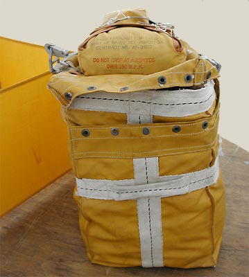 |
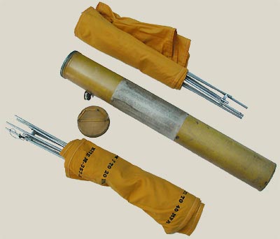
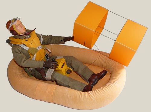
Stowage 13. The radio No. 1 kit should be stowed in a convenient position in the aircraft so that it can be removed quickly from its stowage in an emergency.This position is laid down in the relevant aircraft Air Publication, Vol. 1. On ditching, the radio should be taken into the dinghy in accordance with the particular aircraft dinghy drill. Like all the rescue material of the United States, this padded bag is yellow orange with a base of 12-15 in 15 in height. This bag contains the following accessories : ** A watertight radio equipped with an aerial W 148 to emit manually in Morse or to transmit S.O.S automatically, the reel and the magneto are built-in the radio. ** Two sealed metal boxes, referred M 315 B, contain the components necessary to make the gas for the balloon. ** A small sealed metal box with the balloon referred M 278 A. ** The cellular kite M 357a stowed in its bag with instructions of use. ** A signal lamp M 308 B ** A spanner for the tight buttons of the radio. ** A spare antenna W 148 with a reel of braided copper wire. ** An inflating tube. ** Three small padded bags to wedge this material. Kite (Stores Ref. 51/161) 14. The kite is used to suspend the aerial or antenna a aloft. It is a collapsible box-kite measuring 17 x 17 x 36 inches when assembled. Complete instructions for its assembly and use are given on the cylindrical container in which it is stowed. The cloth on the kite is |
treated to make it moisture-proof, and a section is filled with kapok to, give the kite water-buoyancy. Continual soaking, however, will eventually saturate the kapok, and the kite will sink. 15. So that the kite can be stowed in a relatively small space, the longerons are divided at the centre. Assembling the equipment 16. Remove the transmitter from its bag, and the kite from its container. The aerial reel door is located on the front panel of the transmitter and this door is opened by the removal of a cotter pin. In some models the door can be kept open by placing this pin in holes provided for it at the door hinge. 17. Take enough slack from the reel to attach to the kite. Rotate the antenna brake knob until there is a slight tension on the reel. Unscrew the cap marked GROUND and remove the ground wire reel. Pay out the wire into the water, the cap will act as a weight to keep it submerged. The farther away from the coast the transmitter is operated the better will be the "earth" provided by the ground wire. |
 |
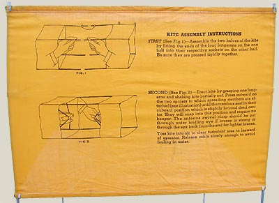 |
hand in through the centre. Push outward on the hinged spider to spread the four upright longerons. When these have been sufficiently extended they will lock into position. Repeat the procedure for opening the opposite end of the kite. Stop pushing on the spiders as soon as they are felt to jump. 19. At one corner of the kite there are two eyelets marked 7 to 20 M.P.H. and 15 to 40 M.P.H. respectively, the wind velocity must be estimated to enable the aerial wire clasp to be fitted into the correct eyelet. If in doubt use the eyelet indicated for low wind velocity. Avoid allowing the kite to fall into the water. 20. When the kite is airborne, maintain a steady tension at the brake to prevent the kite from dropping. Pay out the aerial by hand if desired, but ensure that it is at least 175 ft. long while signals are being transmitted. If possible pay out the whole 200 ft. of aerial. Ensure that the wire does not kink while it is being unreeled, as a strong tug by the kite might cause the wire to break. 21. Never allow the aerial to drag in the water while signals are being transmitted, endeavour to keep it as nearly vertical as possible. Attach the aerial securing cord to the dinghy and fix the aerial lead-in to the aerial. |
22. When it is desired to dismantle the kite push in the spiders and allow it to collapse. Note…. The aerial must never be raised or left up during lightning as it might cause severe injury to personnel. |
23. Now prepare the transmitter for operation in the following manner. Remove the cap located at the top centre and insert the crank which is stowed in the well in the back panel. Tighten the thumb screw. The leash must not be broken. 24. The operator now sits in the dinghy with the transmitter securely strapped between his legs and the front panel facing away from him. Operation Radio transmission 25. Set the selector switch marked RADIO and LIGHT, so that the radio half of the pointer is at the AUTO 1 or AUTO 2 position (fig. 1). Rotate the crank in a clockwise direction at approximately 80 r.p.m. When sufficient speed has been attained, the speed indicator on the top of the transmitter will light. When that speed has been reached it is ineffective to crank faster. 26. Continue cranking, allowing half a minute for the filament to warm up, and then adjust the antenna TUNE control so that the maximum brilliance is obtained on the TUNE-TO-BRIGHTEST indicator. The approximate position of the TUNE control when the aerial is completely paid out, is marked on the panel, but if a shorter aerial is used the knob will be at a different position on the panel. The indicator will flash on and off with the transmitter signals, thus indicating when a signal is actually being radiated. In bright sunlight, therefore, the indicator should be shaded so that its degree of brilliance can be observed. 27. With the RADIO-LIGHT switch in the position marked MANUAL, the operator may send his own telegraphic transmissions. 28. To give rescue parties an opportunity to take bearings, operate the transmitter at least every half-hour. Use of signal lamp 29. The signal lamp may be used for visual signalling at night if an aircraft is heard. This does not require an aerial. Remove the transmitter and lamp from the bag, fit the crank handle, and plug the lead from the lamp into its socket above the left corner of the control panel. Strap the transmitter between the legs, set the RADIO-LIGHT selector switch |
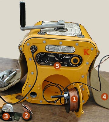 |
1) : Antenna reel |
|
| knob so that the end marked Light points either to AUTO 1 or AUTO 2 or MANUAL. Now crank the transmitter at a speed to give the maximum brilliance of the signal lamp. 30. To telegraph with the signal light, place the selector LIGHT so that it points to MANUAL. Turning the crank, manipulate the push button key. Note. No radio transmission occurs when the signal light is used. |
|
 |
31. Now strap the lamp on the head as follows : 1) If the lamp has a flat lens it will be directional, therefore strap it to the forehead, or else shine it on the water and rotate it like a beacon. 2) If the lens is dome-shaped it is non-directional, - and should be strapped on the top of the head with the straps under the chin. Extract of manual : SEARCH AND RESCUE AIRBONE EQUIPMENT 86. Before attempting to launch the kite, it is advisable to fur the mainsail and to bring the boat round until the wind is on the beam. It will be found that by making use of the foresail and tiller the boat can be brought to lie across the wind. Extract of manual : STANDARD DINGHY RADIO KIT N°1 Notes to Operators 1. The transmitter is low powered and operates on medium frequency, therefore to obtain maximum range it requires a high aerial and an efficient earth. An inefficient earth (as when used on land) seriously reduces range. |
Kit 1/6eme made by Wokipi |
Range of transmitter : At sea : 250-500 miles In boat (centre large lake) : 50-150 At edge of lake : 30 -50 (earth lead in water) On land : 5-10 (earth lead buried in moist ground) In the last two conditions the TUNE TO BRIGHTEST indicator may not function; if it does not, then turn the TUNING control to the indicator mark. 2. Aerial height is obtained by suspending the aerial wire from a kite (fig. 2). In conditions that prevent the kite from being used, the aerial Type 420 should be used instead. The Type 420 aerial is part of the dinghy equipment, it is not included in the radio kit. In the Q-type dinghy it is stowed in a pocket on the buoyancy chamber. Do's and Don'ts 3.DO use as much of the aerial as possible. DO get the aerial as near vertical as possible. DO transmit at least every 30 minutes for periods of not less than 5 minutes. Note…. If the time is known, the transmission should be timed at 15-17 and 45-47 minutes past each hour, as at these times listening-out is done by ship borne operators on 500 kc/s. |